Dr. Mark E. Barkey
Professor of  Aerospace Engineering and Mechanics
The University of Alabama
Structural Durability and Fatigue Performance Group

Pressure Testing of Recyclable Transmission Lines (RTL's)

Toledo Metal Spinning Cone Results


T1 cone
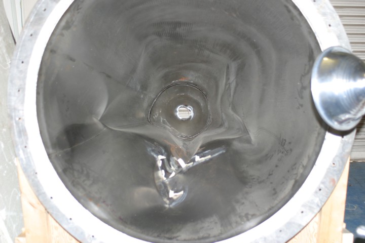
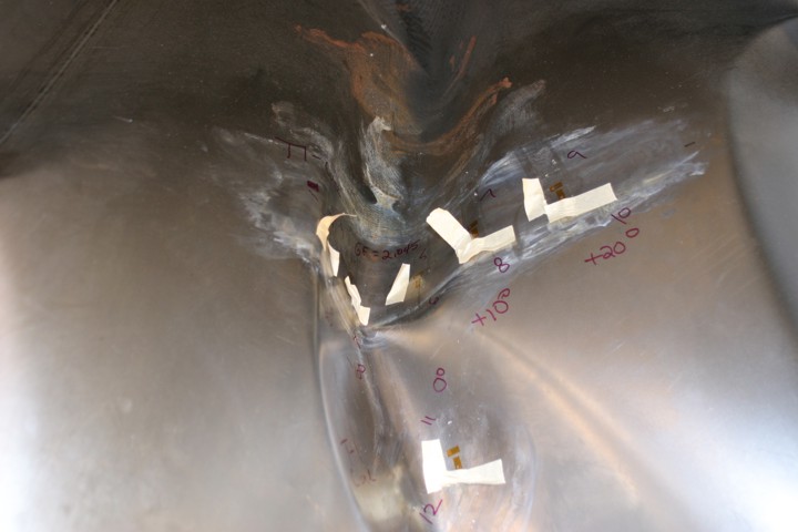
The first TMS cone (desginated T1) has been instrumented with twelve strain
gages over a sector of the cone.  Using the top flange of the cone for reference,
the gage pattern is centered at about 62° from the weld seam.  The center of the
pattern is denoted the 0° location, and there are hoop and axial gages at -20°, -10°,
0°, 10°, 20°  located at a depth of 25 inches into the cone along the cone wall.
Additionally, a gage pair is located at about 18 inches into the cone along the zero
degree location.

It is not easy to determine where the cone may fail due to buckling, but since some
stiffening effect may be expected at the weld seam, the sector of the cone near the
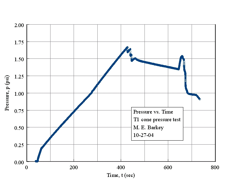
weld may buckle instead.  The testing was done October 2004.


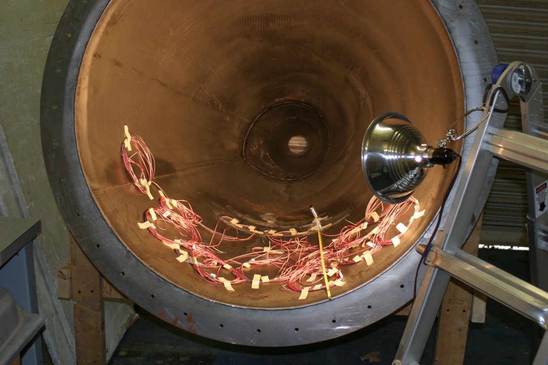
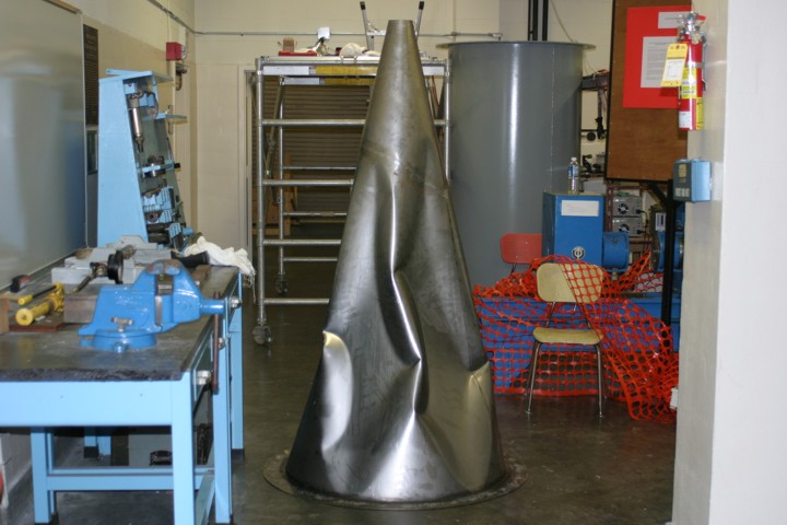
T1 cone instrumented with strain gages.
The cone was tested and the testing time, pressure reading, and strain gage readings were digitized
and saved to a computer file.  Below is a plot of the pressure vs. time during the test.  A buckling
instability was achieved at the highest point pressure in this plot--about 1.64 psi [note: this value is
subject to the accuracy of the pressure gage].

The following is a video that was made during and after the test.  Note that the buckling of the segments
did not happen all at once, but rather each "boom" heard in the video corresponds to a segment of
the cone "snapping" into its buckled postion.  T1-Video

Below are pictures of the cone after the test.  The picture immediately below is in the same orientation
as the picture of the unbuckled cone immediately above.