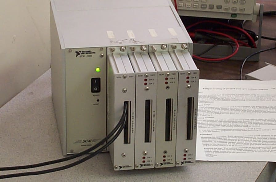
The data acqusition systems are used for both teaching and research. There are currently three National Instruments SCXI systems, with one each devoted to the servo-hydraulic fatigue testing lab, undergraduate mechanics of materials laboratory course, and the graduate experimental solid mechanics course. However, when each system is not in use for its primary duty, it is applied to the other tasks as needed. Data Acquisition Systems
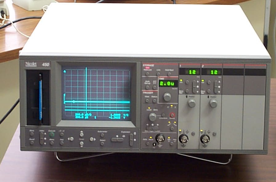
In addition, the lab contains a high speed Nicolet 450 Digital Oscilloscope and a Nicolet 3091/310 Oscilloscopes.

SCXI-1000 System
National Instruments www.ni.comDescriptions of the SCXI modules are listed at the end of this section.
System No. 1 Fatigue and Durability Lab
The computer is a P3-1000 Gateway Computer with 384MB RAM running Windows 2000
Professional.The module in the SCXI chassis slot 4 is multiplexed to a PCI-6052E (PCI) card. The manual
for this product is located should be available on the NI website.The computer also contains a PCI-6711 (PCI) anaolog output card for D-A device control. The 6711
manual should be available on the NI website. This is cabled to a CB-68LP 68 pin terminal block.The primary purpose of this computer is to collect data from an MTS 407 servo-controller (which
is connected to an MTS 810 test frame) with a PC communication card and to send load signals
to the Program-In port of the servo-controller.The system runs with NI-DAQ 6.8.1 and applications built with the Labview Application Builder.
SCXI-1000 Chassis
slot 1 1121 module 1327 terminal block
slot 2 1121 module 1321 terminal block
slot 3 1121 module 1321 terminal block
slot 4 1121 module 1321 terminal blockSystem Notes: (These notes are mostly for my own use.)
slot 1 is used for receiving signals from the MTS 407 backplane BNC connectorsThis web-page should be updated to reflect the present state of the SCXI system.
channel 0: stroke signal (407-AC1)
channel 1: load cell (407-DC2)
channel 2: extensometer (407-DC3)
channel 3: currently unusedNetwork completion on this 1121 module is disabled. Disabled network completion is required
for signals that are externally conditioned, such as +/- 10V signals, or for an externally excited
full bridge. (Enabled network completion is needed for quarter-bridge strain gage applications,
which will also require an external dummy resistor.)The output of the 407 is a signed 10 V signal proportional to the full scale value of the
407 channel. For example, for the 10,000 lb load range, the DC2 conditioner will read 10 V
at 10,000 lbs. On the 50,000 lb load range, the DC2 conditioner will -2 V at -10,000 lbs.Care must be used when selecting terminal block and SCXI-1121 gains as well as the cutoff filter
value. In particular for 12-bit A-D boards, the stroke signal may need to be amplified by gains of greater
than 1 if the displacement (piston/stroke position) signal is very small. This can be difficult to estimate a priori,
especially when conducting fatigue tests at small cyclic displacement amplitudes but with large
mean displacements (e.g. rivited coach peel specimens). Setting gains that are two small will lead to
signal resolution problems. Gains that are too large will lead to overscale problems.The PCI-6052E has 16-bit resolution (1 part in 65536 in unipolar mode). The present setting of the board is for +/- 10 V external signal associated with the native +/- 5 V bi-polar operational mode. The 6052E manual
reports a relative accuracy of 115 uV.When the MTS 407 is set for the 10,000 lbs = 10 V range, the (theoretical) resolution of 0.115 lbs is achieved.
For the 50,000 lbs = 10 V range, this leads to a (theoretical) resolution of 0.575 lbs. These resolution values
would likely not be achieved due to the signal conditioning in the MTS-407 among other things, but the point is that the 6052E A-D board is no longer the issue it was when using the AT-MIO-16E-10.Thus it should not be necessary to use any signal ampification when using the 6052E to capture load and stroke information from the MTS 407 on the 810 frame, while using the 16-bit 6052E board. If a relative accuracy of better than 0.115 lbs is needed for a testing application, then a smaller capacity load cell should be used.
If input signals of greater than 10 V need to be measured, then the 1327 terminal block attenuation switches must be set. The 1327 is an eight channel terminal block, but only the even numbered channels (0,2,4,6) are used with the 1121 modules which map them to the 1121 channels 0,1,2,3. This should also be true for the
1305 BNC terminal block.For fatigue testing, it is advisable to keep the cutoff filter level set to 10 kHz. The filter is a low-pass filter, and will reject any frequencies above the cutoff. Thus, the 4 Hz filter level is usually not a good choice, as my typical fatigue testing frequencies of the MTS 810 system are 5 Hz and above, depending on the specimen compliance. Electical noise in the materials testing lab appears not to be a source of concern at the testing frequencies that can be reasonably achieved.
The modules in slots 2-4 are setup for quater bridge strain gage use. The settings are for a gain of 1000,
3.33 V excitation level, volage mode, 10 kHz filter.
The current settings of the modules are listed below:
slot 1 1121 module 1327 terminal block
terminal block gain ( 1 / attenuation value) of 1.0 (all channels)slot 2 1121 module 1321 terminal block
disabled completion network (all channels)
two stage gain settings of D, A => 1 x 1 = 1.0 (all channels)
filter of 10 kHz (all channels)enabled completion network for quarter bridge strain gages (all channels)slot 3 1121 module 1321 terminal block
two stage gain settings of A, D => 100 x 10 = 1000.0 (all channels)
3.33 V excitation in voltage mode (all channels)
filter of 10 kHz (all channels)enabled completion network for quarter bridge strain gages (all channels)slot 4 1121 module 1321 terminal block
two stage gain settings of A, D => 100 x 10 = 1000.0 (all channels)
3.33 V excitation in voltage mode (all channels)
filter of 10 kHz (all channels)enabled completion network for quarter bridge strain gages (all channels)System No. 2 Mechanics of Materials Lab
two stage gain settings of A, D => 100 x 10 = 1000.0 (all channels)
3.33 V excitation in voltage mode (all channels)
filter of 10 kHz (all channels)The computer is a P5-100 Gateway Computer with 80MB RAM running Windows 2000 Professional.
The primary purpose of this computer is to collect data for Mechanics of Materials Laboratory
experiments.The system runs with NI-DAQ 6.8.1 and applications built with the Labview Application Builder.
SCXI-1000 Chassis
slot 1 1121 module 1321 terminal block
slot 2 1121 module 1321 terminal block
slot 2 <empty>
slot 4 1122 module 1322 terminal blockThe module in slot 1 is multiplexed to an AT-MIO-16E10 (ISA) card. The manul for this board should be on the NI website.
System No. 3 Experimental Solid Mechanics Lab/VI Development System
The computer is a Pentium Pro Gateway Computer with 192MB RAM running Windows 2000.
The primary purpose of this computer is for the Experimental Solid Mechanics
Lab and for development of VI's for use on all of the systems.The system runs with NI-DAQ 6.8.1, Labview Full Development System 6.1 and the Labview
Application Builder.SCXI-1000 Chassis
slot 1 1121 module 1321 terminal block
slot 2 1121 module 1321 terminal block
slot 2 <empty>
slot 4 1122 module 1322 terminal block
The module in slot 1 is multiplexed to an AT-MIO-16E10 (ISA) card. The manul for this board should be on the NI website.
The computer also contains an AT-AO-6 (ISA) anaolog output card for D-A device control. The manual for this board should
be on the NI website. This is cabled to a 1302 terminal block. Note: when resolving IRQ conflicts for this board,
the jumper settings on the board and in the Windows 2000 device manager must both be changed.The AT-MIO-16E10 has 12-bit resolution (1 part in 4096 in unipolar mode). The present setting of the board is for +/- 10 V
external signal associated with the native +/- 5 V bi-polar operational mode. This effectively cuts the resolution in half to 1 part
in 2048 or 4.88 mV.This board was originally used with the MTS 407 in the fatigue and durability lab. The table mentioned below may be
helpful for comparison purposes to the 6052E board.The table below can be helpful for determining gain settings (board gain multiplied by the terminal block attenuation). The values are
theoretical, and the actual values will depend on the device and signal conditioning in the MTS-407 among other things.
Bi-polar mode for 10V = 10,000 lbs / 0.5 in. / 0.15 in. on the MTS 407
OS = Overscale Value (max measureable 407 input)
RES = Resolution = MAX / (2048)
Gain / Max 407 input V Load OS/RES (lbs) Stroke OS/RES (in.) Exten. OS/RES (in.) 1 / 10V 10,000 / 4.88 0.500 / 244e-6 0.150 / 73.2e-6 2 / 5 V 5,000/ 2.44 0.250 / 122e-6 0.0750 / 36.6e-6 5 / 2 V 2000 / 0.977 0.100 / 48.8e-6 0.0300 / 14.7e-6 10 / 1V 1000 / 0.488 0.0500 / 24.4e-6 0.0150 / 7.32e-6 20 / 0.5 V 500 / 0.244 0.0250 / 12.2e-6 0.00750 / 3.66e-6 100 / 0.1 V 100 / 0.049 0.00500 / 2.44e-6 0.00150 / 0.732e-6

