the initial state of the RTL cone and the buckled mode-shapes of the cone using
a laser scanner. The critical buckling load of structures is often very dependent on
the initial state of the structure. If there are any pre-existising defects, the critical
buckling load will be lower than predicted for a "perfect" structure. The buckled
mode shapes can be measured for comparison to numerical analysis and strain
determination.
A laser scanner has the ability to measure distance from a laser
emitter/receiver unit
using only laser light--therefore making a non-contact measurement.
This page was
made to highlight the features and procedures for the laser scanner.
Laser Scanner BasicsQuestions or Comments about this project?--please contact me.
Laser Scanner in Operation
Results of Pre-test Scans
Results of Mode-Shape Scans
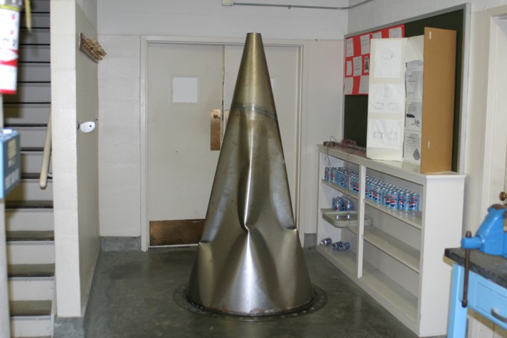
Photos of the Collapsed Cone
The laser scanner that was selected was the AR4000-LIR
with a scanning mirror,
close focus optics, and a high-speed
interface card, from Acuity.
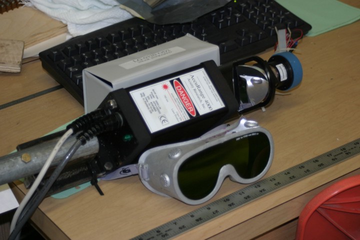
AR4000-LIRThe AR4000-LIR emits a laser beam that is in the near infra-red region, and is
invisible to the human eye. The LIR option was recommended since the cones
were made out steel, with a dulled surface. Although the beam is invisible to the
human eye, some relatively inexpensive digital camcorders have the ability to
"see" the beam. I used a Panasonic PV-DV402D mini-DV digital camcorder that
has the MagicVu feature, which is basically an infra-red detector mode.This camera was extremely useful for verifying the operation of the laser and
for positioning the laser beam. And, since the laser is a Class IIIb device, it
gave me confidence that personel were not in the path of the laser beam. However,
as a precaution to inadvertent exposure, I also wore a proper set of laser safety
goggles matched to this laser's wavelength.The scanning mirror is a high speed rotating mirror with a driving motor and
angular encoder. The mirror is slanted on a 45° angle so that the laser beam
takes a 90° turn. This was a very useful feature for this project, since the
natural positioning of the laser head lends itself to mounting in downward
directed position--in this case, the laser could be mounted downward, and the
mirror directed the laser beam to the wall of the cone. The rotating mirror is
connected to a bracket that obstructs the laser for a relatively small angular
range. In instances were it was important to measure the entire cone, the
laser head itself was turned 180° and remounted so that the measurements
could be repeated.The dimensions of the cones were such that the laser scanner had to make distance
measurements over about a six-foot length in which the radius of the cone varied from
20 inches at the top, down to 2 inches as the bottom. Therefore the close-focus optics
were a necessity, and additionally, the laser scanner was factory calibrated for this
distance range.The AR4000 can communicate to a computer by either a serial communications
port (like an external modem) or by a special high speed interface card. Information
on the pinouts is also provided if some other data acquisition method is used.
For this project, the high speed interface card was used since sample programs
were provided that commanded the laser unit and read the distance and angular
encoder data from the mirror. A Labview driver was not available for this card,
although the sample program was run as an external command from Labview to
enable pseudo-integration of the laser system with other data acquisition systems.
Using the top of the cone as a reference for a cylindrical coordinate
system, the laser
scanner basically measured the R and Theta coordinates of the cone
wall. The depth
into the cone, the Z-dimension, was determined using a string pot
transducer that was
attached to the laser scanner bracket and read with a National Instruments
SCXI system.
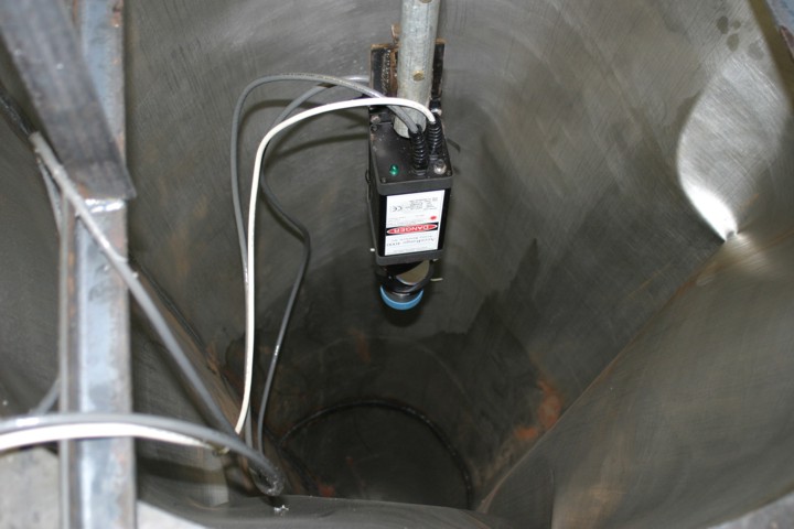
The laser scanner was mounted to a "home-made"
linear bearing that allowed the
scanner to be dropped into the depth of the
cone at approximately the center of
the cone. A sequence of R-Theta scans
were made a various depths into the cone,
as far as the linear bearing would allow.
This video was made using the Panasonic mini-DV
camera described above:
laser line scanner video and shows
one of the R-Theta scans using the laser
and scanning mirror.
The laser scanner was used to determine the initial shape.
A scan was conducted
at each inch along the depth of the cone. More information
about this particular
test can be found on this page: T6.
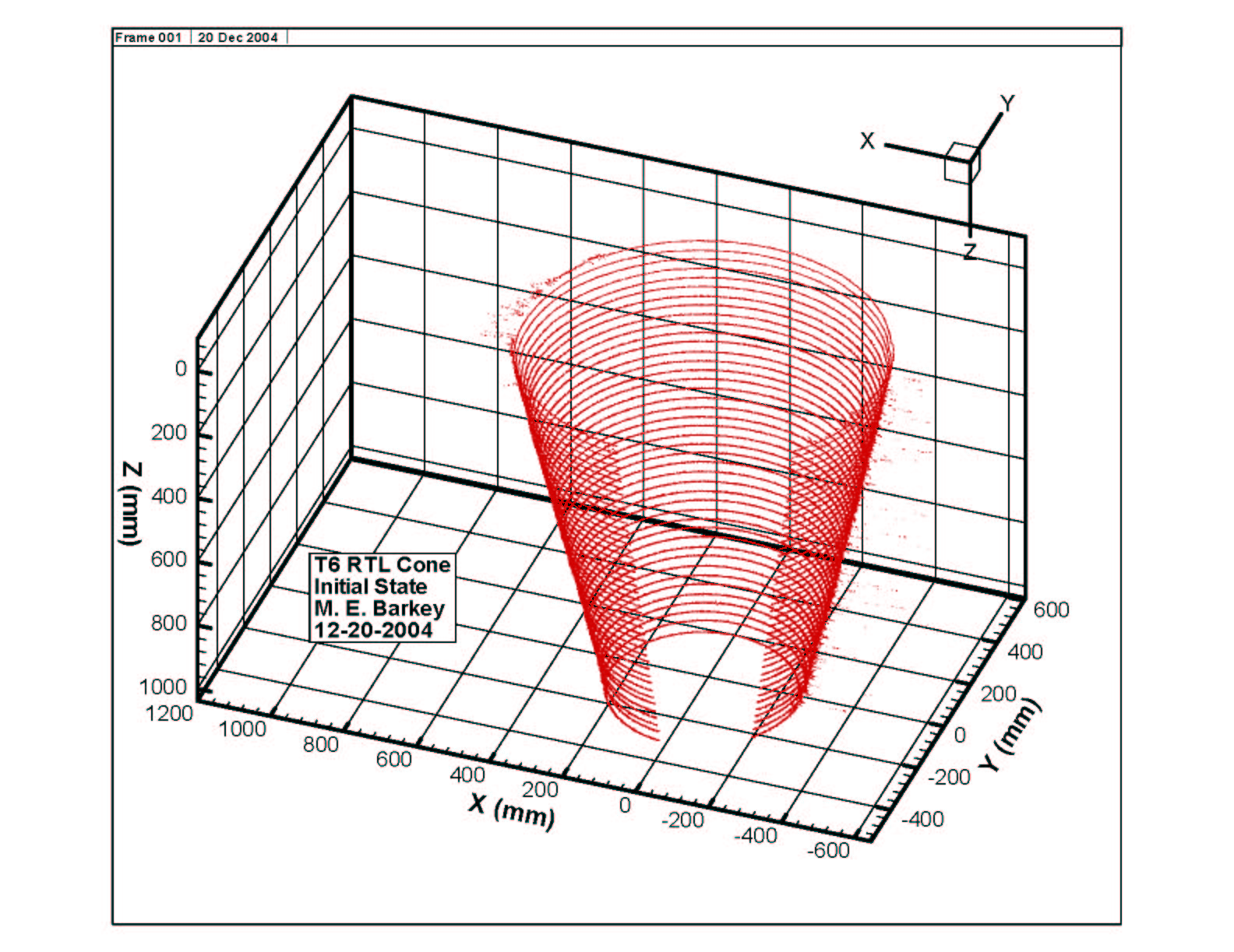
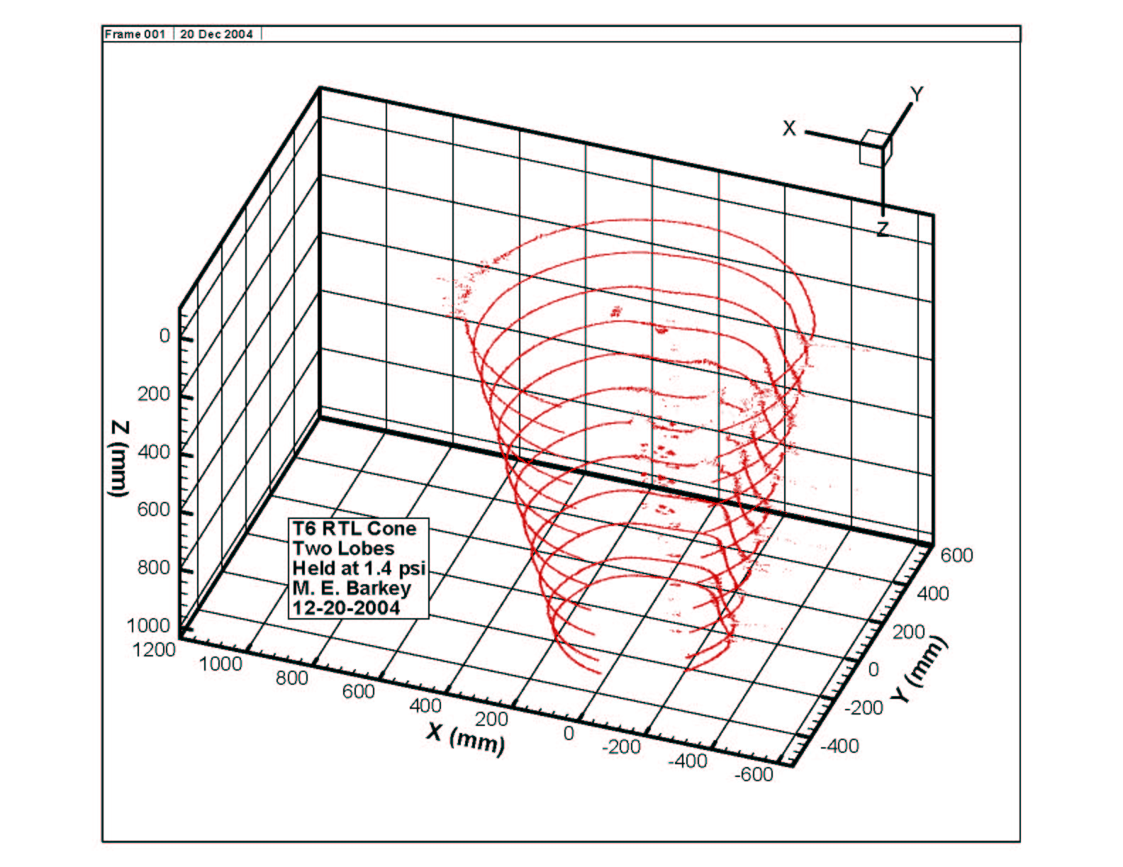
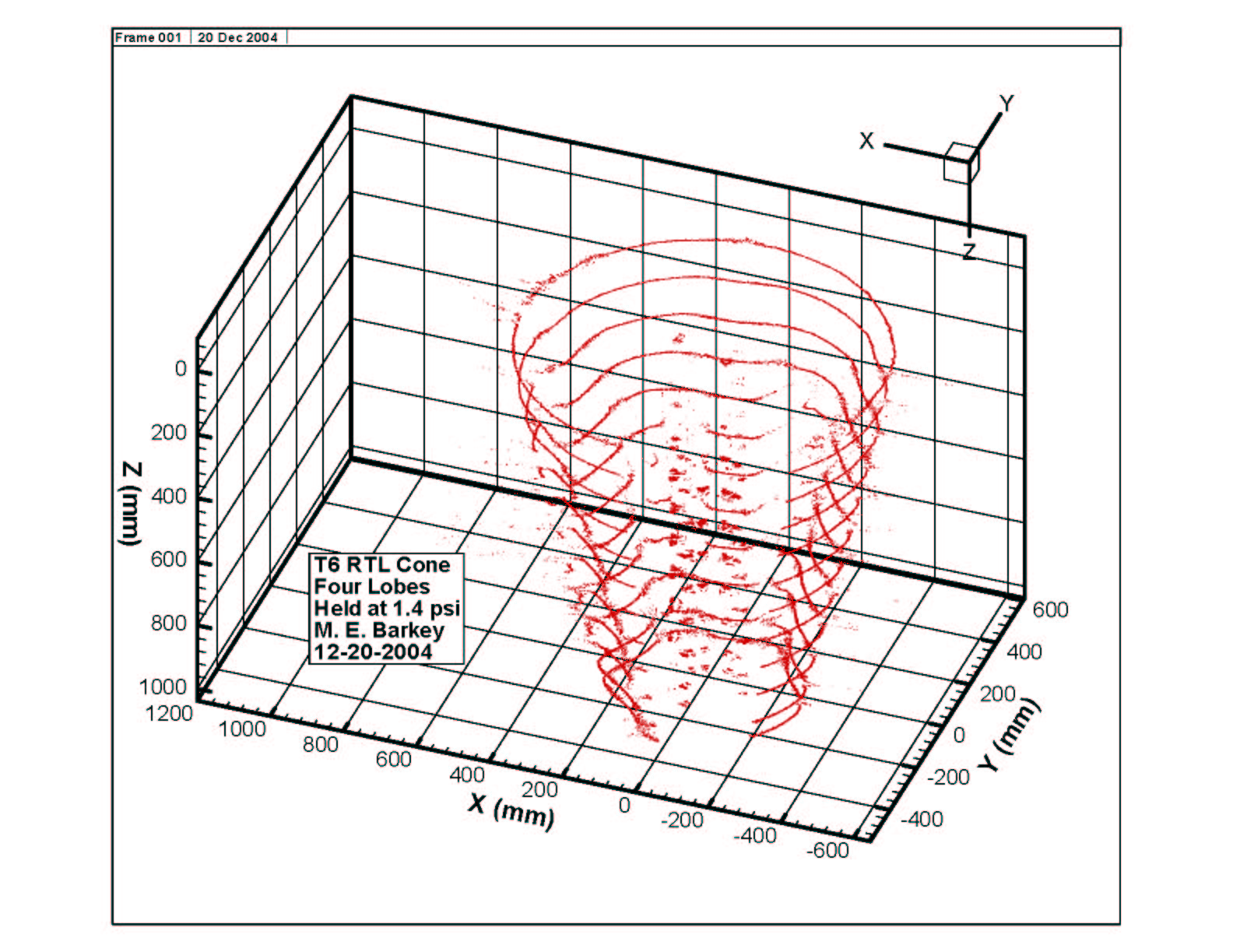
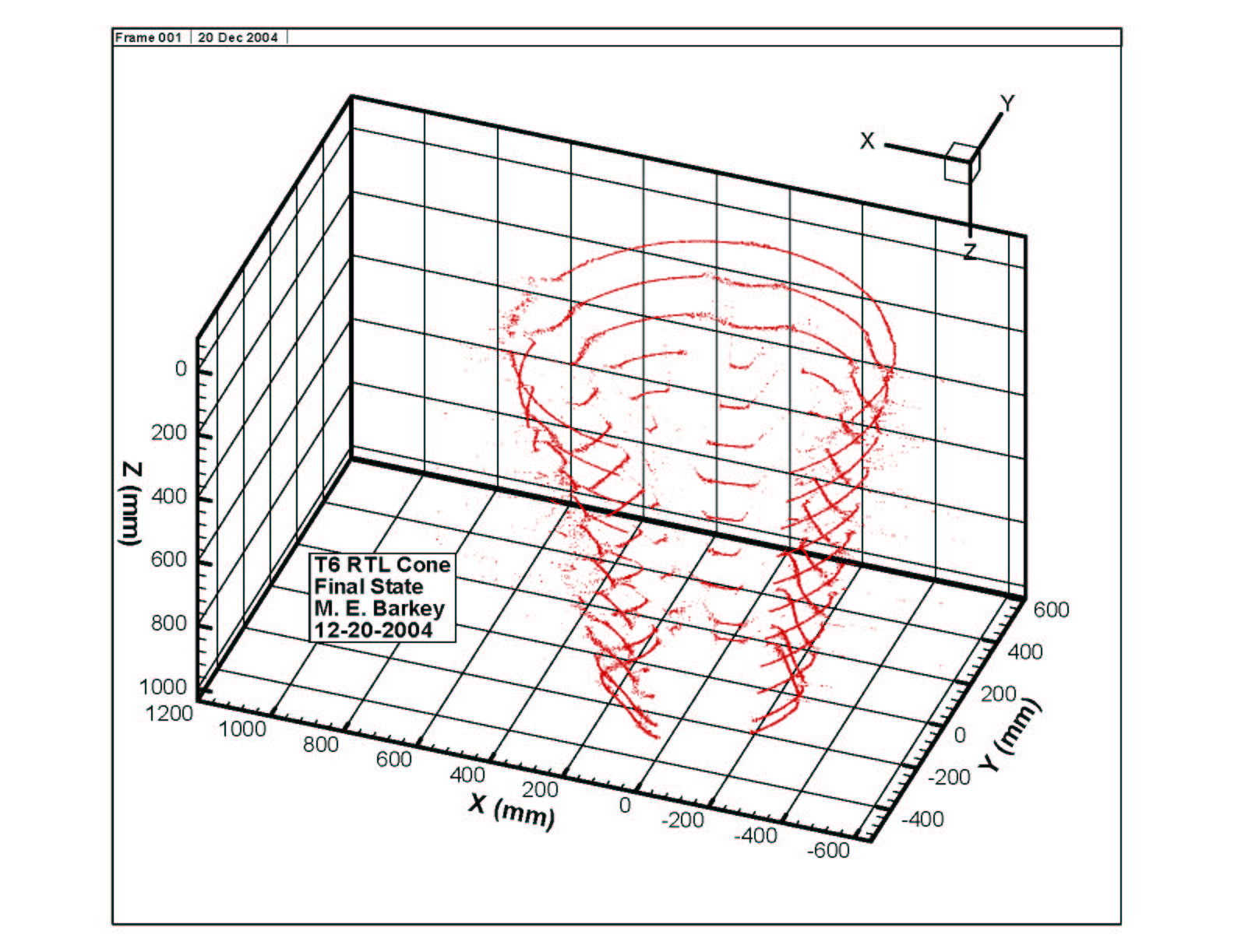
The following three figures show the results
of the scans as portions of the cone began to buckle. The
first plot is after the initial formation
of two "lobes" of buckled cone. The second figure is after a total
of four lobes, and the last plot is at zero
pressure after the cone had reached its collapse load.
As the deformation became more severe, the
laser scanner was unable to get a line of sight to every
part of the cone, so some spurious data was
introduced. Most of this has been filtered out, but some
remains and can be seen in the figures.